
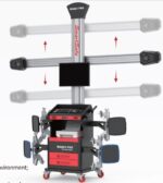
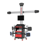




Car Wheel Alignment Machine WA861 X-861
35.000,00 SAR Original price was: 35.000,00 SAR.24.000,00 SARCurrent price is: 24.000,00 SAR.
The X-861 Series 3D Wheel Aligner is the perfect solution for automotive service centers looking for high precision and efficiency in wheel alignment. This device features advanced 3D vision technology that allows for the measurement and adjustment of wheel angles using high-performance cameras without the need for field calibration. The device enables ultra-accurate angle measurements and provides quick and reliable results. With a database containing over 20,000 car models from around the world, the X-861 ensures high measurement accuracy and overall vehicle performance improvement. It also helps reduce fuel consumption and increase tire lifespan. This device is the ideal choice for any service center aiming to provide professional and reliable service to its customers.
Launch Saudi Arabia takes pride in being the authorized distributor of Launch products in the Kingdom of Saudi Arabia, offering the X-861 Series 3D Wheel Aligner along with integrated services that include professional installation, ongoing technical support, and comprehensive warranty. With a specialized team of experts, we guarantee you the highest level of service and precision in every wheel alignment measurement and adjustment. Choose Launch Saudi Arabia to achieve the best performance for your automotive service centers with long-term support to ensure your complete satisfaction.
214 in stock
 Maya / Pre-sale Questions
Need Help? Contact Us via WhatsApp
The X-861 Series 3D Wheel Alignment Machine is an advanced device that utilizes 3D vision technology to accurately measure and adjust wheel angles, ensuring vehicle stability and enhancing performance. The machine is equipped with high-performance cameras for automatic detection of alignment parameters and is factory-calibrated, eliminating the need for on-site calibration. The X-861 offers a wide range of measurements, including front and rear wheel angles, camber, steering angle (SAI), and other crucial angles. It features a comprehensive database with over 20,000 car models worldwide. This device is ideal for service centers seeking fast and accurate wheel alignment solutions, contributing to improved tire life, reduced fuel consumption, and enhanced comfort and safety during driving.
Introduction to the Wheel Alignment Device
The X-861 Series 3D Wheel Alignment Device is used to test wheel angle parameters and provide a reference for the specifications set by the manufacturer. By comparing the two sets of standards, the operator can adjust the vehicle’s wheel parameters to a reasonable range, ensuring optimal driving performance and preventing unnecessary tire wear.
When is Wheel Alignment Needed?
Wheel alignment is an essential procedure for maintaining the vehicle’s performance and safety, as it helps achieve the perfect balance between the vehicle’s tires and the road surface. The need for alignment indicates problems that may affect vehicle handling and tire safety. The following indicators suggest when wheel alignment may be necessary:
- Vehicle drifting to one side when the steering wheel is released: If you notice the vehicle pulling to one side without direct steering input, it may be due to misaligned wheel angles, affecting stability.
- Uneven tire wear: Uneven tire wear is a clear sign of an alignment issue, as it reduces tire lifespan and increases costs.
- Steering wheel vibration or difficulty in control: When there is vibration, excess weight, or abnormal lightness in the steering wheel at high speeds, it indicates the need for wheel alignment.
- After changing tires or replacing suspension parts: When replacing tires or making changes to suspension components like shock absorbers, wheel alignment should be checked to ensure optimal performance.
- After an accident: Even minor accidents can affect wheel alignment. It is recommended to check and adjust the alignment after any accident to ensure safety.
- After driving a new vehicle for 3,000 kilometers: New cars may require realignment shortly after use to ensure maximum performance.
- Regular vehicle maintenance: Wheel alignment should be part of the regular maintenance schedule to keep the vehicle performing well and ensure tire safety.
The Importance of Wheel Alignment Using the X-861 Series 3D Wheel Alignment Device
Wheel alignment is one of the most important maintenance procedures that ensures the performance and safety of a vehicle. The wheel alignment device helps improve vehicle control, extend tire life, and reduce fuel consumption. Below are the key benefits that highlight the importance of wheel alignment:
- Improved Driving Stability:
Wheel alignment helps maintain vehicle stability while driving, especially at high speeds or on winding roads, providing the driver with a safer and smoother driving experience. - Reduced Fuel Consumption:
When the wheel angles are misaligned, the vehicle requires more effort to move, leading to increased fuel consumption. Aligning the wheels contributes to reducing this consumption and achieving better efficiency. - Extended Tire Life:
Uneven tire wear shortens their lifespan. Aligning the wheels reduces this wear, saving on tire replacement costs and increasing their longevity. - Improved Vehicle Performance:
Wheel alignment achieves balance between all the wheels, enhancing the overall performance of the vehicle and ensuring a comfortable and stable drive. - Ensures Road Safety:
Wheel alignment helps reduce the risk of accidents caused by vehicle drift or difficulty in control, thus enhancing road safety. - Preserves Suspension System Components:
Misaligned wheels negatively affect the suspension system, leading to the wear of mechanical parts. Aligning the wheels protects these components and reduces maintenance costs.
The main angles for wheel alignment
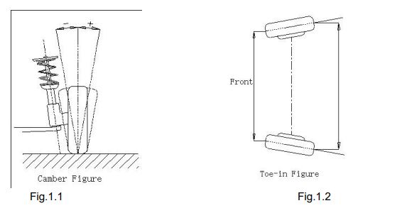
Wheel alignment angles are the relative angles between the vehicle’s chassis components that contribute to the stability of the car’s movement and reduce tire wear. The main wheel alignment angles include: Camber angle, Toe-in angle, Caster angle, and Steering Axle Inclination angle.
Camber Angle
The camber angle is the angle made by the wheel relative to the vertical line when viewed from the front or rear.
- Negative Camber: If the wheel tilts toward the chassis, the angle is considered negative.
- Positive Camber: If the wheel tilts away from the chassis, the angle is considered positive.
Importance of Camber Angle
- Determining contact points and force between the wheel and road: The camber angle directly affects the contact point between the wheel and road, impacting tire grip and wear.
- Reducing uneven wear: Proper camber adjustment distributes the load on the axle, reducing uneven tire wear and preventing excessive bearing wear.
- Compensating for suspension system distortion: The camber angle helps correct angles caused by mechanical distortions in the suspension system or changes resulting from high loads.
- Improving steering stability: Similar to a motorcycle, where the body tilts to define direction, the camber angle helps improve steering stability.
- Enhancing stability during straight-line driving: Together with the Toe-in angle, camber adjustment improves stability during straight-line driving and reduces uneven tire wear.
- Prolonging tire and bearing life: Without camber, wheels may tilt inward under full load, increasing the likelihood of uneven tire and bearing wear. Adjusting the camber angle helps extend the lifespan of both.
The camber angle is one of the primary angles that must be adjusted to achieve vehicle stability and reduce tire wear. Proper adjustment of this angle enhances driving experience and overall vehicle performance.
Toe-in Angle
The Toe-in angle is the angle at which the front wheels tilt when viewed from above. If the front edges of the wheels tilt slightly toward each other, this is called Toe-in, expressed as a positive value. If the edges tilt outward away from each other, it is called Toe-out, expressed as a negative value.
Toe-in Angle Calculation
The total Toe-in value is the sum of the Toe-in angles for each wheel and is defined as the angle between the center lines of the tires.
Importance of Toe-in Angle
- Improving stability during straight-line driving: The Toe-in angle helps compensate for tire tilting inward or outward caused by camber angle and road resistance, ensuring stability during straight-line driving.
- Reducing unwanted friction: Adjusting the Toe-in angle helps improve force distribution between the tires and the road, reducing uneven friction and abnormal wear.
- Enhancing driving experience: Proper Toe-in adjustment contributes to better vehicle steering and more accurate control, making driving more comfortable and safe.
- Prolonging tire life: Adjusting this angle helps reduce tire stress, increasing its lifespan and saving costs associated with tire replacement.
The Toe-in angle is one of the main alignment angles, playing a significant role in enhancing vehicle stability and reducing tire wear. Regular inspection and adjustment of this angle are recommended to maintain vehicle performance and safety.
Steering Axle Inclination (SAI) Angle
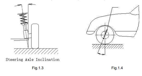
Steering Axle Inclination is the angle formed by the steering axis with the vertical line when viewed from the front.
Importance of Steering Axle Inclination (SAI):
- Even load distribution on bearings: The correct inclination angle helps distribute the load evenly across the bearings in the wheel alignment system, extending their lifespan and reducing the likelihood of damage.
- Improved steering control: The proper inclination angle contributes to enhancing the driver’s ability to control the steering wheel, improving the vehicle’s response during maneuvers.
- Restoring vehicle to straight position after turning: The correct inclination angle helps the vehicle return to a straight position after turning the steering wheel, ensuring stability while driving.
- Reducing stress on the axle: Without the correct inclination, forces from the vehicle’s weight and road reaction could place excessive stress on the axle, potentially leading to damage over time.
Notes on Steering Axle Inclination:
- The steering axle inclination angle is set during the design of the vehicle’s suspension system.
- Typically, this angle is not adjustable in maintenance workshops.
The steering axle inclination is a crucial factor affecting the vehicle’s stability, bearing lifespan, and steering control. While it is usually not adjustable in most cars, maintaining the suspension system in good condition ensures optimal performance.
Caster Angle The caster angle is the angle at which the front steering axis tilts forward or backward relative to the vertical line when viewed from the side.
- Positive Caster: If the steering axis tilts backward, the angle is positive.
- Negative Caster: If the steering axis tilts forward, the angle is negative.
Importance of Caster Angle:
- Improved straight-line stability: Positive caster helps maintain stability when driving straight, as the steering axis intersection with the road surface is ahead of the contact point of the wheel, similar to the functioning of shopping cart wheels.
- Easier return to straight direction after turning: The greater the caster angle, the easier it is for the vehicle to return to straight-line driving after a turn, improving driving experience.
- Balance between stability and steering ease: A larger caster angle enhances stability but may make steering heavier. Usually, caster angles in vehicles range from 1 to 4 degrees, balancing stability and ease of control.
Steering Axle Inclination (SAI)
The Steering Axle Inclination (SAI) is the angle formed by the steering axle with the vertical line when viewed from the front.
Importance of Steering Axle Inclination (SAI):
- Even Load Distribution on Bearings:
The correct inclination angle helps distribute loads evenly across the bearings in the wheel alignment system, prolonging their lifespan and reducing the likelihood of damage. - Improved Steering Control:
The proper inclination angle contributes to improving the driver’s ability to control the steering wheel, enhancing the vehicle’s responsiveness during maneuvers. - Restoring the Vehicle to Straight Position after Turning:
The correct inclination angle helps the vehicle return to a straight position after steering, enhancing stability during driving. - Reducing Stress on the Axle:
Without the correct inclination angle, the vehicle’s weight and road reaction forces may place excessive stress on the axle, potentially leading to its damage over time.
Notes on Steering Axle Inclination:
- The steering axle inclination is determined during the vehicle’s suspension system design.
- Typically, this angle is not adjustable in maintenance workshops.
The steering axle inclination is a fundamental factor affecting the vehicle’s stability, bearing lifespan, and steering control. Although it is not adjustable in most cars, maintaining the suspension system in good condition ensures optimal performance.
Caster Angle (Caster)
The caster angle is the angle at which the front steering axis tilts forward or backward relative to the vertical line when viewed from the side.
- Positive Caster:
If the steering axis tilts backward, the angle is positive. - Negative Caster:
If the steering axis tilts forward, the angle is negative.
Importance of Caster Angle:
- Improved Stability in Straight-Line Driving:
A positive caster angle helps maintain vehicle stability during straight-line driving by positioning the steering axis intersection point in front of the wheel’s contact point with the road, similar to how shopping cart wheels function. - Easier Return to Straight Direction after Turning:
The greater the caster angle, the more the vehicle can return to the straight driving position after turning, improving the driving experience. - Balance Between Stability and Steering Ease:
A larger caster angle enhances stability but may make steering heavier. Typically, caster angles in vehicles range between 1 to 4 degrees to achieve a balance between stability and ease of control.
Toe-out Angle When Turning
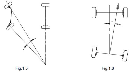
Toe-out Angle When Turning is the difference between the steering angles of the two front wheels when turning right or left by 20 degrees.
Characteristics of Toe-out When Turning:
- The inner wheel angle is always larger than the outer wheel angle during a turn.
- The difference between the angles is approximately two degrees.
Importance of Toe-out When Turning:
- Facilitates Maneuvering: The Toe-out angle allows the inner wheel to turn at a greater angle than the outer wheel, enabling the vehicle to turn smoothly and effectively.
- Reduces Turning Resistance: The angle helps reduce the resistance caused by the difference in the wheel angles during a turn, making steering easier and improving performance during cornering.
Caster and Toe-out when turning are essential factors that affect vehicle stability and steering ease. It is recommended to adjust them precisely to ensure optimal vehicle performance.
Thrust Angle
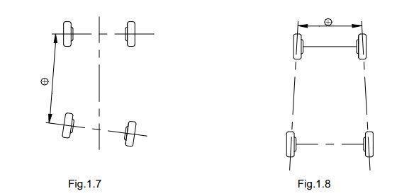
The thrust angle is the angle between the centerline of the vehicle and the thrust line, which represents the actual direction in which the vehicle moves.
Positive Thrust Angle:
When the thrust line is tilted to the left of the vehicle’s centerline.
Negative Thrust Angle:
When the thrust line is tilted to the right of the centerline.
Importance of Thrust Angle:
- Ensuring alignment of the thrust direction with the centerline of the vehicle:
If the thrust angle does not align with the centerline, it can cause the vehicle to drift during driving, as the front and rear wheels pull in different directions. - Adjusting rear toe (Rear Toe Adjustment):
If the thrust angle is not zero, it is recommended to adjust the rear toe angle to correct the misalignment and ensure the vehicle moves straight.
Wheelbase Difference
The wheelbase difference is the angle between the line connecting the center points of the rear wheels and the line connecting the center points of the front wheels.
Positive Difference:
When the distance between the center of the right wheels is larger than the distance between the left wheels.
Negative Difference:
When the distance between the center of the left wheels is larger than the distance between the right wheels.
Importance of Wheelbase Difference:
- Improving driving stability:
A significant wheelbase difference can cause the vehicle to drift and be unstable while driving. - Analyzing wheelbase using technical specifications:
If wheelbase data is available from the vehicle’s technical specifications, it can be converted into an angle for accurate evaluation.
Tread Difference
Tread difference, also known as track width difference, is the angle between the line connecting the contact points of the left wheels with the ground and the line connecting the contact points of the right wheels.
Positive Difference:
If the distance between the center of the rear wheels is greater than the distance between the center of the front wheels.
Negative Difference:
If the distance between the center of the front wheels is greater than the distance between the center of the rear wheels.
Importance of Tread Difference:
- Analyzing lateral stability:
This measurement helps assess the vehicle’s stability during turns. - Evaluating the vehicle’s engineering accuracy:
The vehicle’s technical specifications can be used to convert tread difference into an angle, improving the accuracy of the analysis.
Left/Right Lateral Offset
Lateral offset is the relative difference in the lateral position between the left (or right) rear wheel and the left (or right) front wheel.
Positive Lateral Offset:
If the left (or right) rear wheel is located outside the left (or right) front wheel.
Negative Lateral Offset:
If the rear wheel is inside the front wheel on the same side.
Lateral Offset Angle:
This is the angle between the thrust line and the line connecting the center of the front and rear wheels on the same side (left or right).
Importance of Lateral Offset:
- Improving load distribution:
Evaluating the lateral alignment of the axles ensures even load distribution. - Increasing driving stability:
Reduces sideways drift during driving.
Axle Offset
Axle offset is the relative difference in the lateral position between the front and rear axles of the vehicle.
Positive Axle Offset:
If the rear axle tilts to the right compared to the front axle.
Negative Axle Offset:
If the rear axle tilts to the left.
Axle Offset Angle:
This is the angle between the thrust line and the line connecting the axle width differences.
Importance of Axle Offset:
- Improving the vehicle’s engineering performance:
Ensures proper axle alignment for greater stability while driving. - Reducing lateral drift:
Reduces tire wear caused by misaligned axles.
Delay
Delay is the relative difference between the position of wheels on the same axle in the longitudinal direction of the vehicle.
Positive Delay:
If the right wheel on the same axle is positioned behind the left wheel.
Negative Delay:
If the right wheel is positioned in front of the left wheel.
Delay Angle:
This is the angle between the wheel center line and the vehicle’s longitudinal center line.
Importance of Delay:
- Ensuring driving stability:
Helps prevent vehicle drift due to differences in wheel positions. - Improving control:
Enhances the vehicle’s dynamic performance, especially during acceleration or braking.
Advanced Functions and Features in the X-861 Wheel Alignment Machine
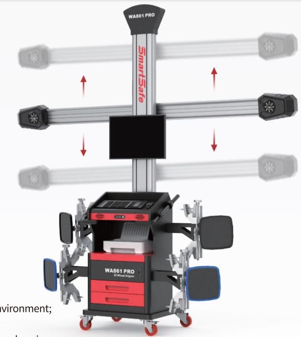
- New 3D Visual Measurement (Three-Dimensional Computer Visual Measurement): The X-861 machine utilizes a high-performance camera that automatically detects alignment parameters (angles) with high precision. What sets this device apart is that the camera is pre-calibrated during the manufacturing stage, meaning there is no need for manual calibration on-site during installation, saving both time and effort.
- Passive Target: The targets used in the X-861 device do not contain any electrical components or wires, ensuring ease of use and supporting high durability and reliability in the long term. This design reduces the need for routine maintenance or electrical issues, enabling users to operate the device effectively without technical problems.
- Adjustable Height Installation: The X-861 device can be installed at any height according to the user’s preference. This flexibility allows users to adjust the device to suit their environment, making it easy to use in workshops or automotive service stations.
- X-861 3D with Auto Focus: The X-861 3D with auto focus enables the device to automatically detect the height of the target. It then follows the lift motion up and down to ensure the device stays at the optimal height for operation at all times. This feature makes the inspection process smoother and more accurate while saving time on calibration and manual adjustments.
- X-861 3D with Fixed Height: This model allows for manual height adjustment while ensuring that the device follows the lift motion perfectly. This feature guarantees that the device remains at the ideal height during the alignment process, improving measurement accuracy.
- Simplified Test Procedure: The testing process with the X-861 device is extremely simple thanks to the user interface, which is supported by guided instructions. These instructions make it easy for anyone, regardless of experience level, to perform a test and adjust wheel angles accurately.
- Complete Parameter Measurement: The X-861 device is capable of measuring all the necessary parameters for wheel alignment, such as:
- Front and rear Toe-in angles.
- Front and rear Camber angles.
- Thrust Angle.
- Caster Angle.
- SAI/Kingpin Angle. Additional measurements, such as Wheelbase, Tread, and Diagonal Angles, can also be added.
This ensures precise and comprehensive measurements for wheel alignment and improved vehicle performance.
- Large Database: The X-861 device features a database containing over 20,000 records of cars from around the world. It also allows users to add new data as needed. This extensive database ensures the device can accommodate a wide range of vehicles and provides flexibility for entering new cars.
- Historical Data Storage for Client Management: The device can securely store historical test data to facilitate workshop or center client management. This allows tracking of vehicle performance over time and provides guidance for future reports based on previous performance.
- Real-time Help System: The X-861 device comes with a real-time help system that assists users who need guidance or clarification while using the device. This ensures a smooth and problem-free user experience, with support available at any time.
The X-861 3D Wheel Alignment Machine is an advanced and integrated solution for measuring and adjusting wheel angles. It offers high precision, ease of use, and multiple customization options to meet the needs of all users. With its large database, intelligent auto-focus and height systems, and real-time assistance, this device is the ideal choice for specialized automotive service centers and wheel alignment workshops.
The technical specifications of the 3D X-861 Wheel Alignment Machine.
| Specification | Details |
|---|---|
| Power Supply | AC 1PH AC220V±10% 50Hz or AC110V±10% 60Hz |
| Computer Host | Smartsafe custom from the brand |
| Monitor | 24/32-inch color LCD screen from Great Wall |
| Toe-in Angle | Test range: 0~±20º |
| Camber | Test range: 0~±20º |
| SAI/Kingpin Angle | Test range: 0~±20º |
| Caster Angle | Test range: 0~±20º |
| Thrust Angle | Test range: 0~±5º |
| Rim Diameter | From 10″ to 23″ |
Environmental Requirements for the 3D X-861 Wheel Alignment Machine
| Requirement | Details |
|---|---|
| Ambient Temperature | 0~50℃ |
| Relative Humidity | ≤85% |
| Lighting Condition | No direct infrared light on the targets |
| Platform Lifting Height Difference | Front/Rear lifting height difference less than 2mm |
The working principle of the 3D X-861 wheel alignment machine
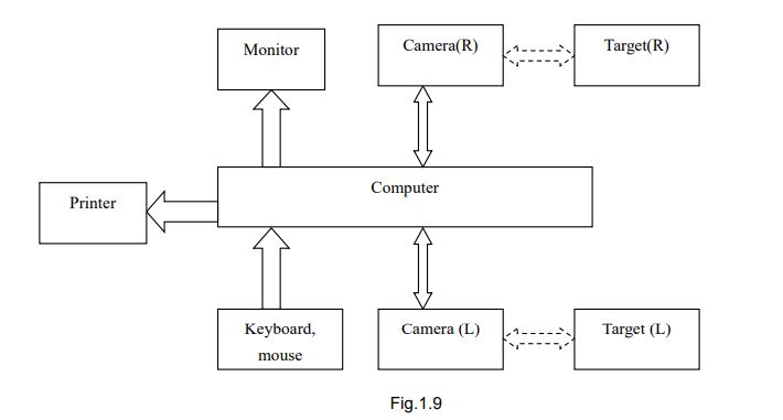
The working principle of the X-861 Series 3D Wheel Aligner, as illustrated in Figure 1.9, is based on dividing the entire system into two main categories:
- Data Acquisition:
- In this stage, advanced cameras are used to capture precise measurements of angles and wheel alignment parameters. The system determines the wheel angle relative to agreed-upon reference standards using 3D measurement technologies.
- Data Processing:
- After data collection, the information is processed using the integrated computer system. The data is analyzed to determine whether the alignment parameters are within optimal ranges or require adjustment.
The goal of this process is to provide accurate measurements that allow the user to make necessary adjustments to wheel angles, ensuring optimal driving performance and preventing abnormal tire wear.
Detailed Working Principle of the X-861 Series 3D Wheel Aligner:
Data Acquisition Category:
- This system consists of two high-resolution cameras and four targets.
- The cameras (one camera on each side of the vehicle) capture images of the targets mounted on the wheels.
- These images are sent to the Data Processing category.
- The targets are mounted on the wheels using clamps, allowing the wheel’s position to be calculated based on the point defined by the target.
- This information is used to precisely determine the wheel alignment parameters.
Data Processing Category:
- The Data Processing category is the core component of the X-861 system. This category includes the computer system, power supply system, and interface system.
- The primary function of this category is to execute the operator’s instructions, automatically guide the measurement process, process the data, and display the results alongside the original data from the manufacturer (OEM).
- The measurement results are displayed to the operator with precise guidance for making necessary adjustments to the vehicle.
- Finally, the final report is printed.
Database Importance:
- Since the X-861 system needs to compare measured data with manufacturer (OEM) data to provide accurate guidance to the operator on necessary adjustments, the database is an essential part.
- The X-861 database contains wheel alignment data for over 20,000 vehicle models worldwide.
- Additionally, the database provides reference data and enables the operator to input and save alignment parameters for new vehicle models.
Key Benefits:
- High accuracy in data collection using advanced cameras and non-electrical targets.
- Data processing power allows for accurate reports that assist in making the right adjustments.
- A comprehensive database containing alignment data for thousands of vehicles worldwide.
Physical Structure of the X-861 Series 3D Wheel Aligner
General Structure:
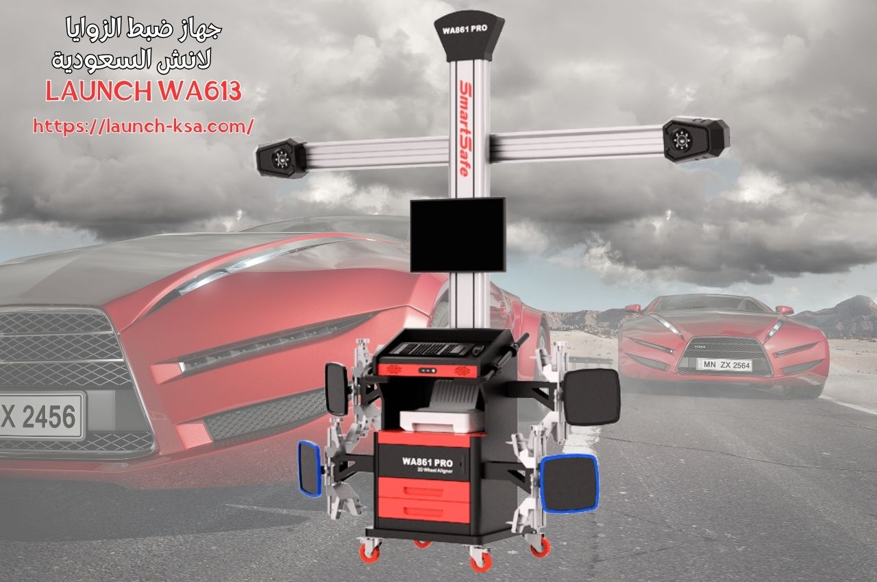
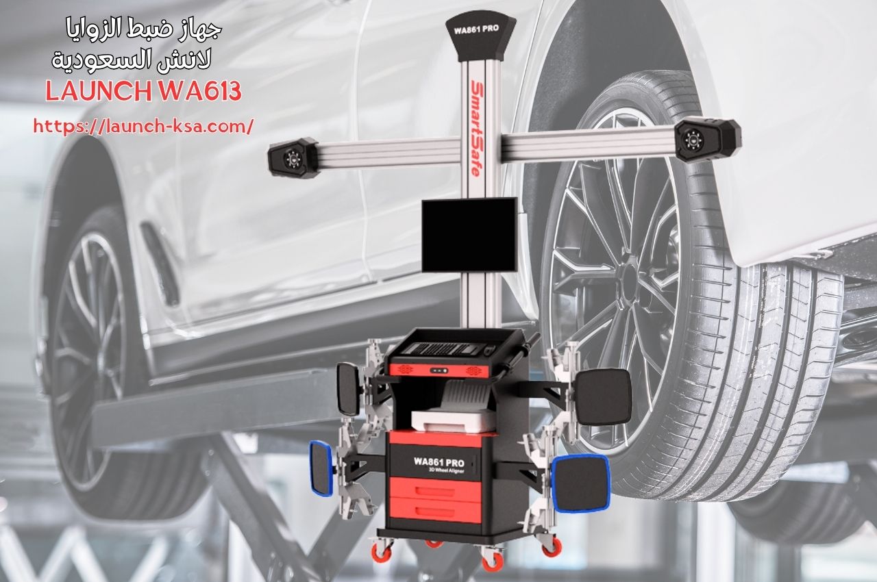
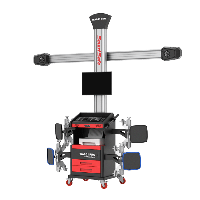
The X-861 Series 3D Wheel Aligner primarily consists of:
- Column Assembly
- Lateral Beam Assembly, including the camera
- Cabinet
- Computer Host
- Monitor
- Printer
- Targets
- Clamps
- Communication Cables
- Turntables – Standard accessory
- Steering Wheel Holder
- Brake Pedal Depressor
Note: The components and accessories for each model of the device may vary. For detailed information, it is recommended to consult with the distributor or refer to the product packing list.
Targets and Clamps:
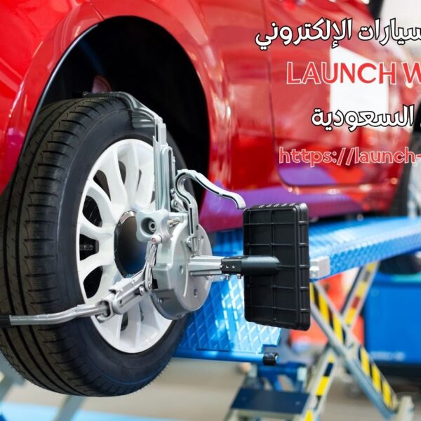
The X-861 Series 3D Wheel Aligner includes 4 targets (with 4 clamps). These targets are essential for collecting raw data for wheel alignment. The cameras capture images of the targets and convert them into processable data. The back of each target has a label that indicates its position.
Communication Cables:
The wheel alignment system includes two cables between the computer and the lateral assembly:
- USB Data Cable
- Power Supply Cable
Note: It is important to maintain these cables in good condition to avoid any damage that may affect the entire system.
Turntable and Transit Bridge:
The X-861 Series 3D Wheel Aligner comes with 2 mechanical turntables. The turntables should be placed in the front wheel position on the lift. Each turntable includes a pair of transit bridges and a pair of brake blocks, which are placed between the turntable and the lift to ensure smooth movement of the vehicle during rolling compensation.
Steering Wheel Holder:
The X-861 Series 3D Wheel Aligner comes with a steering wheel holder. During the test, the steering wheel holder must be positioned as directed by the operator to ensure that the vehicle’s direction remains unchanged during the alignment process.
Brake Pedal Depressor:
The X-861 Series 3D Wheel Aligner includes a brake pedal depressor. This device is used to press the brake pedal to prevent the vehicle from moving during certain measurement stages, such as measuring the caster angle (Caster Swing).
Basic Operating Procedures for the X-861 Series 3D Wheel Aligner
Preliminary Inspection:
- Inquire with the vehicle owner about driving issues, symptoms, and wheel alignment history.
- Collect vehicle information such as country of manufacture, brand, model, year, etc.
- Carefully inspect every part of the chassis, including dust covers, bearings, control arms, ball joints, shock absorbers, tie rods, and steering mechanism for any loose parts or wear.
- Check if the tire pressure, tire size, and tread of the left and right wheels are identical.
- Communicate with the owner if any abnormal conditions are detected.
- Perform a test drive with the owner if necessary to confirm the issue and take necessary actions to ensure measurement accuracy.
Alignment Measurement:
- Begin alignment measurement after completing the preliminary inspection.
Adjustment:
- Based on the measurement results from the alignment process, and in combination with the actual symptoms of alignment issues in the vehicle, refer to OEM data (original manufacturer data) and make necessary adjustments according to the actual situation.
Test Drive:
- After completing the alignment adjustment, perform a test drive to verify if the previously existing symptoms have been eliminated.
- If the problem persists, readjust the settings.
Operating Instructions for the X-861 Series 3D Wheel Aligner
Preparation Before Testing:
- Inquire with the vehicle owner about driving issues, symptoms, and alignment history, and gather information about the vehicle such as the country of manufacture, brand, model, year, etc. Perform a test drive with the owner if necessary.
- Check the locking of the turntables and side sliding plates, then position the transit bridge. Drive the vehicle onto the lift so that the front wheel is in the center of the turntable. Once the vehicle is in the desired position, center the steering wheel and lock it using the steering wheel holder. Place wheel brakes at the rear wheels to prevent the vehicle from slipping, then release the handbrake. After that, lift the vehicle to the required alignment height.
- Carefully inspect every part of the chassis, including dust covers, bearings, control arms, ball joints, shock absorbers, tie rods, and steering mechanism for any loose parts or wear. Then, check if the tire pressure, tire size, and tread of the left and right wheels are identical.
- Install the clamps and targets on the wheels, and secure the clamps.
- Connect the power cable of the X-861 Series 3D Wheel Aligner to a standard three-prong power outlet.
Running the X-861 Series 3D Wheel Aligner Program:
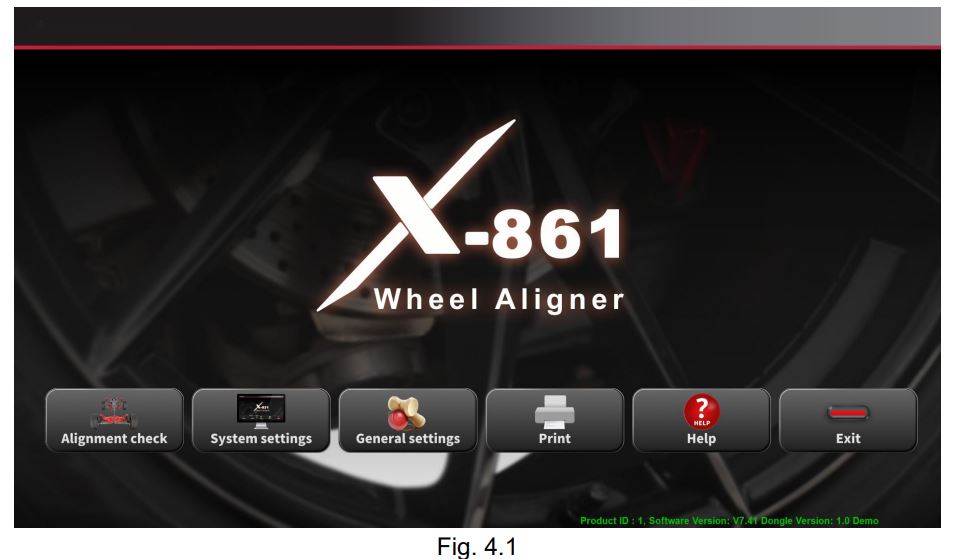
- Power on the device, then turn on the computer. After that, the program’s main interface will load directly.
- The main interface contains six functional buttons:
- Alignment Check
- System Settings
- General Settings
- Print Report
- Help
- Exit
Note: These steps must be followed to ensure accurate results and ease of operation when using the X-861 Series 3D Wheel Aligner.
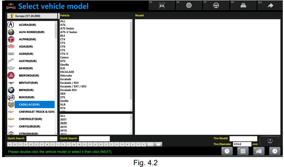
Alignment Check
- Click on [Alignment Check] in the main interface to enter the measurement interface.
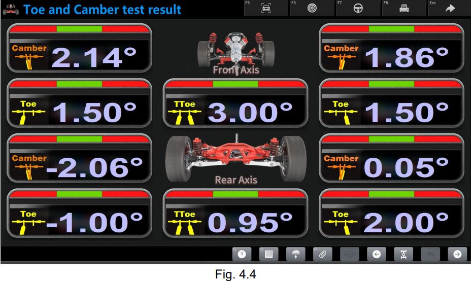
- In the measurement interface, alignment parameters such as Toe angle, Camber angle, Caster angle, SAI/Kingpin angle, etc., will be displayed.
- Follow the on-screen instructions to properly adjust the device and direct it towards measurement.
- Results will be calculated by comparing them with the original OEM data and can be displayed immediately.
- After the measurement is complete, detailed results will be provided, including any alignment errors and correction guidance.
Note: Ensure the wheels are in a stable position and the vehicle is stationary before starting the measurement for accurate results.
Selecting the Vehicle Model
Before starting the alignment measurement, you must select the reference vehicle data. This can be done by selecting the vehicle model from the device’s database. Follow these steps:
- Open the measurement interface in the program after clicking “Alignment Check.”
- Select the vehicle model from the database available in the device. You can select the model by:
- Brand
- Year
- Model
- Country of Origin
- If the vehicle model is not available in the database, you can manually add new data. Ensure the data is entered accurately to guarantee precise measurement.
- Once the correct model is selected or added, the device will load its original OEM data for use in the measurement.
Note: Make sure to select the correct model before starting the measurement to ensure the accuracy of the results compared to the original data.
Navigation Bar
- Access independent measurement steps instead of following the default sequence.
Database Selection
- Select the data record from different database categories, such as:
- Frequently Used
- China
- America
- Europe
- If this is the first time using frequently used specifications, the list will be empty. In this case, data must be imported from the original OEM specifications through the main interface.
- Click on System Management -> Frequently Used Specs to add your data.
Manufacturer, Make, Model List
- Select the desired model from the list to proceed to the next step.
- If this is the first time using the model, the list will be empty. Select a specific manufacturer, then choose the model from the list.
Quick Manufacturer Index Letter Selection Area
- Click on the appropriate letter to quickly select the manufacturer from the list.
- Direct input is not available here.
Quick Vehicle Index
- There is an input box at the bottom of the screen for quick access to the vehicle index.
- For Chinese writing, the first character of the spelling can be entered.
- For English, the first letter of the car’s name in English or more letters can be entered.
Help
- Help provides instructions and tips on how to work in the current page.
Target Monitor
- If a warning appears that the target is obstructed, the reason can be found in the target screen.
- In this screen, the lateral beam height can be adjusted manually or automatically.
Quick Measurement
- If an unexpected exit occurs after pressing the button, or if there is a secondary measurement after the test drive, quick measurement can be used.
- However, the result may be somewhat inaccurate since rolling compensation has not been performed yet.
Next
- If you want the measurement to follow the default sequence, press Next, which follows the steps below:
- Select Vehicle -> Rolling Compensation -> Caster Swing -> Print Report.
Rolling Run-out Compensation
Rolling run-out compensation aims to eliminate errors caused by:
- Physical defects in the rim and tires.
- Inaccurate clamp installation.
The process is performed using the wheel movement axis directly to make adjustments, and the interface for this process is shown below.
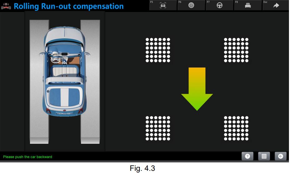
Operating Procedure:
- Installing Clamps and Targets: Install the clamps on the wheels, then attach the targets to them.
- Placing the Transit Bridge: Place the transit bridge in the appropriate location between the turntable and the lift.
- Centering the Steering Wheel: Center the steering wheel and secure it using the steering wheel holder.
- Removing the Brake Pedal Depressor.
- Moving the Wheel Barrier: Move the wheel barrier approximately 15 cm backward (if the wheel diameter is greater than 700 mm, increase the distance accordingly).
- The car must be allowed to move freely within this distance.
- Push the car forward and backward as instructed by the system.
Warnings:
- Before Rolling Run-out Compensation:
- Ensure the steering wheel is firmly fixed to prevent the wheels from swaying, which could lead to an unstable axle alignment.
- When Pushing the Car Forward and Backward:
- Do not obstruct the camera’s view during the process.
- Ensure the push is stable and steady.
- The target must be vertical to the ground at the start. If the target is not in the correct vertical position, it may result in excessive tilt, leading to an unnatural target image.
- After completing rolling run-out compensation, the transit bridge must be removed.
Target Red Color Status:
- Status: A red color on the target indicates that the captured image is not valid for measurement.
- Possible Cause: There may be an obstruction between the camera and the target, preventing the camera from capturing a clear image of the target.
Help and Assistance:
- Help: The help option is available on the current page, providing guidance and tips on how to solve the issue or complete the process correctly.
Target Monitor Screen:
- If an issue occurs, check the cause through the target monitor screen when the system shows a message indicating the target is blocked or not visible.
- Through the screen, you can manually or automatically adjust the lateral beam height to ensure a proper image capture.
Previous Step:
- If you need to re-perform rolling run-out compensation, you can return to the previous step to do it again, ensuring the process is done correctly.
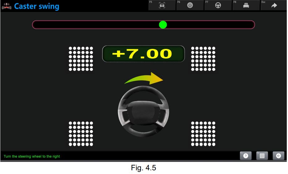
Caster Swing:
- Definition: Caster swing is limited to the front wheels only and includes caster and steering angle (SAI).
Importance of Caster and SAI:
- Steering Angle (SAI): Distributes loads evenly across the bearings, helping to extend bearing life and improve steering control.
- Caster: Helps keep the vehicle moving in a straight line by pushing the steering axis ahead of the contact point of the wheel with the road, providing stability during driving.
Purpose of Caster Swing:
- Achieve better directional stability through the effect of caster, contributing to the vehicle’s movement in a straight line.
- Improve the overall performance of the front axles.
Steering During Swing:
- Adjusting Data: If the effect of caster swing is not considered important, alignment data can be directly adjusted from this page.
- Raising or Lowering the Vehicle: During adjustments, the vehicle can be raised or lowered using the lift. The lateral beam moves with the lift or lowering to maintain the best working condition for the tool.

















ورشة السلام –
الجهاز رائع ومميز شكرا
المهندس –
مجهود رائع شكرا للمساعدة
ورشة العرب –
تعاملكم راقي شكرا مهندس احمد
ورشة جدة –
الجهاز قيمة للمكان
ورشة العراقي –
والله ماقصرتوا وتستاهلوا كل خير مشكورين
اسلام ميكانيكي –
الجهاز مميزاته والنظام ممتاز جدا
ورشة مكة –
من احسن من تعاملت معهم
ورشة النور –
ممتازين جدا ورائعين
ورشة نويبع –
شكرا لتعاملكم والدورة المميزة
الورشة الحديثة بمكة –
احسن ناس تعاملت معاهم شكرا لكم
هودي للسيارات –
مشكورين
ورشة الشعلة –
شكرا لتعاملكم ومساعدتكم لي
ورشة الدمام العالمية –
مشكوووووووورين على الدورة والمساعدة
ورشة نور –
جزاكم الله كل خير ماقصرتوا تستاهلوا نتعامل معاكم 1000 مرة
ورشة العرب –
شكررررررررررررررررررا
محمد علي –
مشكورين ماقصرتوا
رجب الدمام –
اشتريت من شركات كثير بس انتوا احسن ناس في الدعم والمعاملة الحسنة شكرا مهندس احمد
ورشة الفضاء –
جزاكم الله خيرا ووفقكم ماقصرتوا معاي
محمد العتيبي – الرياض –
خدمة ممتازة، الجهاز استجاب بسرعة والتحديث تم في نفس اليوم، أنصح الجميع.
سلمى الحربي – جدة –
الفريق تعامل بلُطف وشرح كل الخطوات بوضوح. التحديث أحدث فرقاً في أداء سيارتي.
عبدالله الشمري – الدمام –
جربت عدة ورش قبل، لكن خدمات لانش الخليج كانت الأسرع والأفضل من حيث الجودة.
نورة القحطاني – مكة المكرمة –
التشخيص كان دقيقاً وأعدّوني تقريراً مفصّلاً. شعرت أنني فعلاً حصلت على قيمة مقابل مالي.
فيصل الزهراني – أبها –
التعامل احترافي جداً، الأسعار واضحة بدون مفاجآت، والجودة ممتازة.
ماجد السبيعي – بريدة –
الخدمة شاملة — ليس فقط جهاز الفحص، بل شرح لك كل ما يلزم بعد التحديث.
أحمد العنزي – الرياض –
أشكر شركة لانش الخليج على الدورة المجانية المفيدة. الشرح كان مبسط وواضح جدًا، وفريق الدعم متعاون لأبعد حد. تجربة تستحق التقدير!
مشعل القحطاني – مكة المكرمة –
شكراً لانش الخليج على اهتمامكم بالعملاء. الدورة كانت ممتازة والمحتوى متقن، والتعامل راقٍ من أول اتصال حتى التسليم.
فهد الغامدي – المدينة المنورة –
شركة مميزة بكل المقاييس. الأجهزة أصلية والجودة عالية جدًا. أشكرهم على الدورة المجانية التي ساعدتني أفهم الاستخدام خطوة بخطوة
Anonymous –
الورشة الألمانية
ورشة الدمام –
خدمة ممتازة ودعم يستااهل
الورشة الألمانية –
مشكووووووورين خدمة ممتازة